ECE 5554 / ECE 4554: Computer Vision Fall 2017
Instructions
Due date: 11:59pm on Monday, October 9 , 2017
Handin: through canvas.vt.edu
Starter code and data: hw2.zip
Deliverables:
Please prepare your answer sheet using the filename of FirstName_LastName_HW2.pdf.
Include all the code you implement in each problem. Remember to set relative paths so that we can run your code out of the box.
Compress the code and answer sheet into FirstName_LastName_HW2.zip before uploading it to canvas.
Part 1: Feature Tracking (50 points)
|
|
In the problem, you will implement a corner detector and feature tracker that track features from the image sequence hotel. Since this is a two part problem, we have included precomputed intermediate results in the supplemental material in case you’re unable to complete any portion. Do not use existing keypoint detectors, trackers, or structure from motion code, such as found on the web, OpenCV and MATLAB Computer Vision Toolbox.
1.1 Keypoint detection (15 points)
Overview
For the first frame, use the second moment matrix to locate strong corners to use as keypoints. These points will be tracked throughout the sequence in the second part of the problem.
Choose a proper threshold so that edges and noisy patches are ignored. Do local non-maxima suppression over a 5x5 window centered at each point. This should give several hundred good points to track.
Write-up
Provide the psuedocode of the corner detector.
Display the first frame of the sequence overlaid with the detected keypoints. Ensure that they are clearly visible (try plot(..., ‘g.’, ‘linewidth’,3) ).
Hint
Useful functions imfilter, gradient
hold on/off : For displaying points overlay on the same figure.
Rubric
5 points for psuedocode of the corner detector.
10 points for displaying the detected corner points on the first frame.
1.2 Feature Tracking (35 points)
Overview
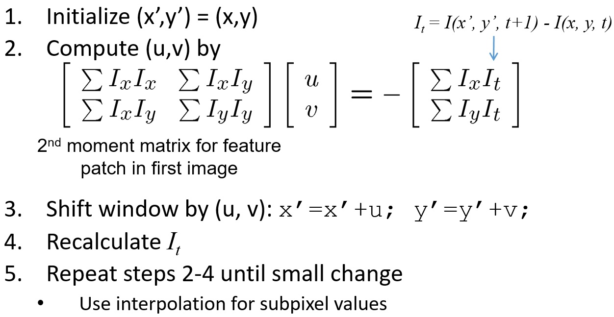
Apply the Kanade-Lucas-Tomasi tracking procedure to track the keypoints found in part 1.1 throughout the hotel sequence.
 |
Some keypoints will move out of the image frame over the course of the sequence. Discard any track if the predicted translation falls outside the image frame.
Write-up
For all the keypoints, display (1) the keypoints at the first frame (as green) and (2) the tracked keypoints at the second frame (as red) on the first frame of the sequence.
For 20 random keypoints, draw the 2D path over the sequence of frames. That is, plot the progression of image coordinates for each of the 20 keypoints. Plot each of the paths on the same figure, overlaid on the first frame of the sequence.
On top of the first frame, plot the points which have moved out of frame at some point along the sequence.
Hint
From the 1st frame to the 2nd frame, use the detected keypoints at the first frame as initialization points. From the 2nd to 3rd frame, use the tracked positions at the 2nd frame as initialization. Note that the tracked keypoints in general are not at integer positions.
For each point, use a window size of 15 x 15.
Useful functions
interp2 : For computing Ix, Iy, I(x’, y’, t+1) when x, y, u, v are not integers.
meshgrid : For computing the indices for interp2
hang on/off : For displaying points overlay on the same figure.
Rubric
15 points for correcting implementation of the Kanade-Lucas-Tomasi tracker and track keypoints from the 1st frame to the 2nd frame.
10 points for tracking keypoints across 50 frames and displaying the trajectories.
10 points for displaying the points which have moved out of frame at some point along the sequence.
Part 2: Shape Alignment (30 points)
 |
Overview
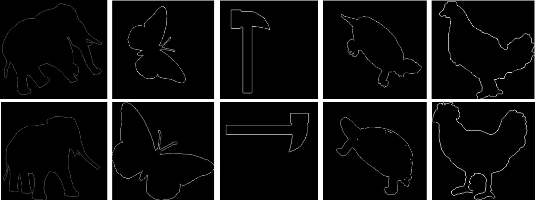
In this problem, you will write a function that aligns two sets of points using global image transformation (similarity, affine, or perspective):
T = align_shape(im1, im2);
where T is a transformation that maps non-zero points in im1 to non-zero points in im2. You may choose the alignment algorithm and the type of (global) transformation (e.g., rigid Euclidean, affine, perspective).
Test your code on the 25 image pairs provided in the supplementary material. We have included functions evalAlignmentAll and displayAlignment to help with evaluation and display.
Write-up
Explain your algorithm, initialization, and model of the transformation
Display the aligned results
Report averaged alignment error
Report runtime
Hint
Use find(im > 0 ) to find the edge point positions.
Rubric
5 points for algorithm explaination.
15 points for a working implementation of shape alignment.
10 points for displaying aligned results, alignment errors, and runtime.
Part 3: Object instance recognition (20 points)
 |
Overview
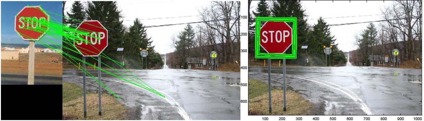
This problem explores the Lowe-style object instance recognition.
Implement the nearest neighbor distance ratio test using the pre-computed SIFT features SIFT_features.mat provided in the supplementary material. The Frame1, Frame2 indicate the 2D position, scales, and the orientation of the descriptors and Descriptor1, Descriptor2 are the correspondin 128-D SIFT features. Use plotmatches to display the matches.
Write-up
Use plotmatches to display
(1) the matches by thresholding nearest neighbor distances.
(2) the matches by thresholding the distance ratio. Describe the differences of (1) and (2).
Hint
Use load('SIFT_features.mat') to load the SIFT features of the two images.
Rubric
10 points: displaying SIFT matches using distance ratio test.
10 points: comparing the difference between matching using nearest distance and distance ratio test.
Graduate points (max possible 40 points graduate credit)
In your answer sheet, describe the graduate points under a separate heading.
Feature Tracking
up to 15 points: Implement a coarse-to-fine feature tracker with at least 3 levels. Test your implementation on frames 10; 20; 30; 40; 50. Compare your results with the single-scale tracker. Display the 6 frames and overlay the tracked keypoints.
up to 20 points: Implement a multi-scale optical flow algorithm using the KLT tracker. Display your flow field from frame 0 to frame 10 using the flowToColor function.
Shape Alignment
up to 10 points: Improve your shape alignment results. For example, you can try using multiple initialization trials (e.g. horizontal flips) and pick the best one. Explain your approach and report improvement.
Object instance recognition
up to 5 points: Use a space partitioning data structure like a kd-tree or some third party approximate nearest neighbor package to accelerate matching. Report the before/after runtime.
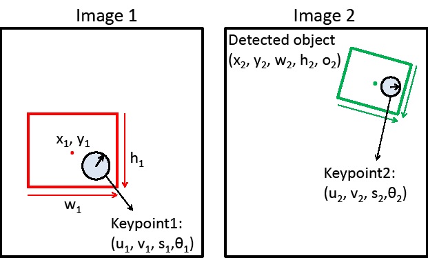
up to 10 points: Suppose that you have matched a keypoint in the object region to a keypoint in a second image (see the figure below). Given the object bounding box center x-y, width, and height (x1, y1, w1, h1) and the position, scale, and orientation of each keypoint (u1,v1,s1, theta1; u2,v2,s2,theta2), show how to compute the predicted center position, width, height, and relative orientation of the object in image 2.
 |
Acknowledgements
This homework is adapted from the projects developed by Derek Hoiem (UIUC)